
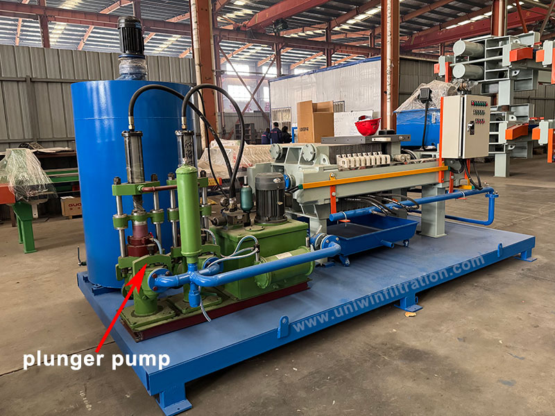
Plunger Pump
A plunger pump is a positive displacement pump widely used in applications involving the transport of liquids, especially in systems such as filter presses, to deliver slurries or liquids to the filter chamber. It achieves the intake and discharge of liquids through the linear motion of a reciprocating plunger within the pump cylinder.
Plunger pumps play a crucial role in feeding materials into filter press systems, especially in industrial filtration applications that process medium- to high-concentration slurries and require high-pressure feed. Their powerful pressure output and stable flow rate make them one of the most commonly used and efficient feed pump types in filter press systems.

Main Structural Components
- Plunger: The core component of the pump, typically made of high-hardness materials (such as stainless steel or ceramic) for wear and pressure resistance.
- Pump Cylinder: The chamber through which the plunger reciprocates.
- Suction and Discharge Valves: One-way valves to ensure unidirectional fluid flow.
- Sealing Assembly: Prevents liquid leakage and improves system pressure stability.
- Drive Mechanism: Typically, an electric motor or hydraulic motor drives a crankshaft, which in turn drives the plunger in reciprocating motion.
Plunger Pump Parameters
| Model | Rated flow quantity (M³/H) | Pressure range (MPA) | Preset pressure (MPA) | Stroke (MM) | Equipped with motor (KW) | Dimensions Length*width*height (M) | In/out pulp flange PN16 |
|---|---|---|---|---|---|---|---|
| YB85-2.8 | 2.8 | 0-2.5 | 2 | 220 | 4 | 1.29*1.05*1.5 | DN50/DN40 |
| YB120-7.1 | 7.1 | 0-2.5 | 2 | 250 | 5.5/7.5 | 1.6*1.15*1.6 | DN80/DN65 |
| YB140-10 | 10 | 0-2.5 | 2 | 250 | 7.5/11 | 1.6*1.2*1.6 | DN80/DN65 |
| YB200-19 | 19 | 0-2.5 | 2 | 250 | 18.5 | 1.7*1.3*1.9 | DN100/DN80 |
| YB250-30 | 30 | 0-2 | 1.8 | 250 | 22 | 1.94*1.6*2.2 | DN125/DN100 |
| YB300-40 | 40 | 0-2 | 1.8 | 250 | 30 | 2.1*1.8*2.2 | DN125/DN125 |
| YB300J-60 | 60 | 0-1.5 | 1.2 | 350 | 37 | 2.1*1.8*2.32 | DN150/DN150 |
| YB300J-60 | 60 | 0-2.0 | 1.8 | 350 | 45 | 2.1*1.8*2.32 | DN150/DN150 |
| YB400-80 | 80 | 0-1.8 | 1.6 | 350 | 55 | 2.48*2.5*2.6 | DN150/DN150 |
| YB400-100 | 100 | 0-1.5 | 1.2 | 350 | 55 | 2.48*2.5*2.6 | DN150/DN150 |
| YB400-120 | 120 | 0-1.2 | 1 | 350 | 55 | 2.48*2.5*2.6 | DN150/DN150 |
Core Working Principle of Plunger Pumps
The working principle of a plunger pump is based on the principle of volumetric change:
- Suction Stroke: The plunger moves backward, creating negative pressure in the pump chamber, and liquid enters the pump chamber through the one-way suction valve.
- Discharge Stroke: The plunger moves forward, the liquid is compressed, and discharged under high pressure through the discharge valve.
This process occurs periodically, thus achieving continuous high-pressure output.
Advantages of Plunger Pumps
- Stable flow rate: Low output flow pulsation, suitable for systems requiring high pressure stability.
- High corrosion resistance: Special materials can be selected to adapt to various operating conditions.
- High adjustability: Flow rate and pressure can be adjusted by regulating speed and stroke length.
Common Application Industries
Mining Dewatering: Filtration of copper and iron ore tailings.
Ceramics/Building Materials: Filtration of ceramic slurry; after drying, it is easy to mold or recycle.
Chemicals/Pharmaceuticals: Treatment of reaction residues or high-concentration waste liquids.
Metallurgical Wastewater: Filtration of heavy metal sludge for volume reduction.
Municipal Sludge Treatment: Improving filtration efficiency and reducing filter cake moisture content.
Usage Precautions
- Seal Maintenance: Long-term operation causes significant wear on the seals; regular inspection and replacement are necessary.
- Cooling System: During high-frequency operation, pay attention to plunger heat management.
- Valve Inspection: Valve malfunctions may lead to backflow or insufficient pressure.
- Lubrication System: Internal components require proper lubrication to reduce wear.